Added a "test pattern" to verify all the connections are secure. To activate the test pattern you simply hold down the blade activation button when you turn on the power switch. To get it out of test mode simply power cycle.
 |
| Routed out a hole for the charging cable |
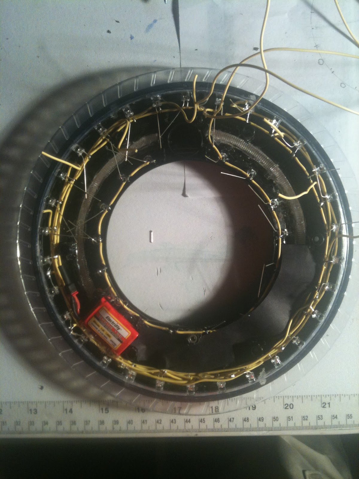
Add a small white rectangle piece of paper to place under the battery so that you can't see the bright red through the translucent C ring. I think I will continue this white top to the inner C ring all the way around because it reflects more of the light outward.
 |
| Bottom half of the blade wired up! |
 |
| Experimenting with opaque paper |
 |
| Charging jack mirrors the factory slider switch hole! |


Looking good. I like how the charging port came out. Are all the negatives on the LEDs touching? Also did you leave anything besides the screw posts when cutting out the unneeded plastic? Keep up the good work.
ReplyDeleteThe blade is made up of two sections of 15 each. Each section has a common "row" wire for addressing in a matrix. The first LED's cathode is connected to the row wire... the second LED's anode is connected to the row wire... and we are done with the first "column" of the matrix. The next column repeats the pattern and so on. I am going to post the schematic right now!
ReplyDelete