https://bitbucket.org/orpex/identity-disc
This is where we are now collaborating on the source code. We can use the wiki to document step-by-step kit installation instructions and feedback.
Monday, February 28, 2011
Sunday, February 27, 2011
Friday, February 25, 2011
Tuesday, February 22, 2011
Monday, February 21, 2011
Sunday, February 20, 2011
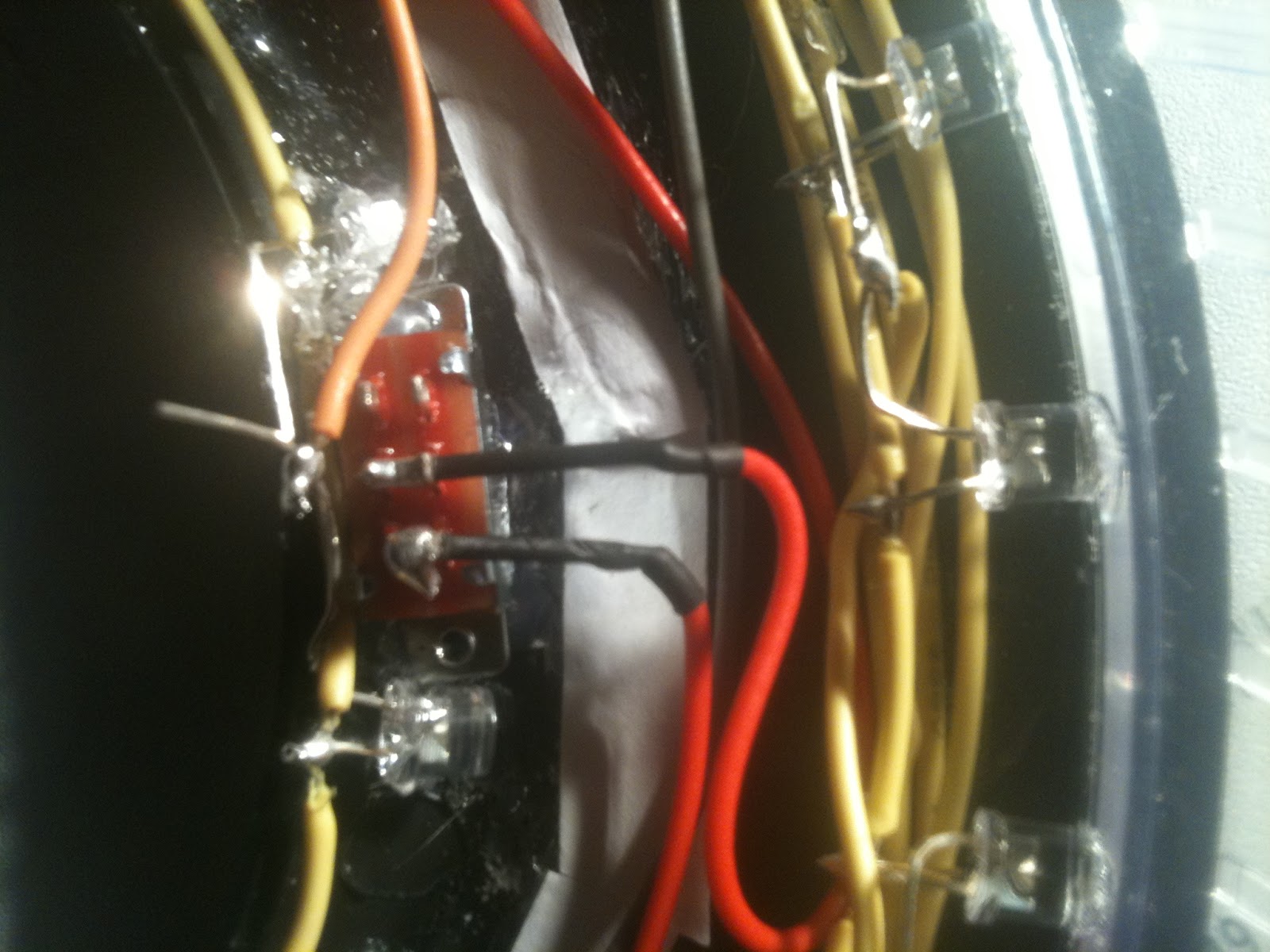
Looking a little better today. Got around the faulty voltage regulator by adding two 33Ω resistors in series. You can also see the first use of my heat-shrink tubing where I connected the wrong set of LEDs and had to rewire it.

 |
| Factory tactile switch has been reinstalled! |
 |
| Got the slider switch replaced and happy... |
Saturday, February 19, 2011
I am devistated!
I managed to burn out two voltage regulators when I hooked up to the LiPo battery for the first time. Anyone have a clue why because I don't! My multimeter says 8.1VDC which is well within the 7-12VDC recommendation from Arduino. Now I have the 8.1VDC hooked up to the 5V port which works but I don't know for how long.
Second issue is that the long-awaited jumpers aren't working out like I thought they would - mainly because they are too long. I tried cutting them back but then they no longer contact solidly which means I will have to solder to the pins.
Minor issue is the slider switch I glued into place - I managed to glue the sliding switch itself by putting too much adhesive on the sides which leaked into the open canal for the switch inside.
Friday, February 18, 2011
Received the balancing chargers today (finally). They have these odd alligator clips permanently attached in addition to having a receptacle for the included 1.5A 12VDC wall adapter.

Unscrew the four screws on the bottom of the unit and the top hinges open. Gently drop the control board out so that you can snip the wires as shown. You will also notice that I spread them apart slightly so that there are no short-circuits!

Thursday, February 17, 2011
The LEDs are a little dimmer than they can safely be operated. A quick Google later I find this from the Arduino site:
Note that the pullup resistors provide enough current to dimly light an LED connected to a pin that has been configured as an input. If LED's in a project seem to be working, but very dimly, this is likely what is going on, and the programmer has forgotten to use pinMode() to set the pins to outputs.So I will take a look at the code again tonight and see if I missed something obvious.
Wednesday, February 16, 2011
 |
| LED matrix schematic |
 |
| Arduino Nano connections (jumpered, no soldering) |
1:  // http://orpex.blogspot.com
2:  // ATmega168
3:  // PIN DEFINITIONS:
4:  // PB1-4 ROW DRIVERS (0-3)
5:  // PC0-5,PD2-3: COLUMN DRIVERS (0-7)
6:  // PD7 BUTTON
7:  #define F_CPU 14745600
8:  #define ROWS 4
9:  #define COLS 16
10:  #include <stdio.h>
11:  #include <inttypes.h>
12:  #include <avr/io.h>
13:  #include <avr/interrupt.h>
14:  #include <avr/pgmspace.h>
15:  #include <util/delay.h>
16:  volatile uint8_t la_row, real_row;
17:  volatile uint8_t la_data[COLS];
18:  inline uint8_t ledarray_get(uint8_t i, uint8_t j)
19:  {
20:   if(i < ROWS && j < COLS)
21:   {
22:    if((la_data[j] & (1<<i)) != 0)
23:    {
24:     return 1;
25:    }
26:   }
27:   return 0;
28:  }
29:  inline void ledarray_set(uint8_t i, uint8_t j, uint8_t onoff)
30:  {
31:   if(i < ROWS && j < COLS)
32:   {
33:    if(onoff)
34:    {
35:     la_data[j] |= (1<<i);
36:    }
37:    else
38:    {
39:     la_data[j] &= ~(1<<i);
40:    }
41:   }
42:  }
43:  //sense variable indicates direction of LED: sense == 1 indicates COL wire must be
44:  //high for LED to turn on. sense == 0, COL wire must be low to turn LED on
45:  inline void ledarray_set_columndriver(uint8_t j, uint8_t onoff, uint8_t sense)
46:  {
47:   // cols 0-5: PC0-5
48:   // cols 6-7: PD2-3
49:   if(j < 6)
50:   {
51:    if(onoff)
52:    { //led on
53:     DDRC |= (1 << (PC0 + j));
54:     if(sense)
55:     {
56:      PORTC |= (1 << (PC0 + j));
57:     }
58:     else
59:     {
60:      PORTC &= ~(1<< (PC0 + j));
61:     }
62:    }
63:    else
64:    { // led off, pins to high impedance
65:     DDRC &= ~(1 << (PC0 + j));
66:     PORTC &= ~(1 << (PC0 + j));
67:    }
68:   }
69:   else
70:   {
71:    if(onoff)
72:    { //led on
73:     DDRD |= (1 << (PD2 + (j-6)));
74:     if(sense)
75:     {
76:      PORTD |= (1 << (PD2 + (j-6)));
77:     }
78:     else
79:     {
80:      PORTD &= ~(1 << (PD2 + (j-6)));
81:     }
82:    }
83:    else
84:    { // led off, pins to high impedance
85:     DDRD &= ~(1 << (PD2 + j));
86:     PORTD &= ~(1 << (PD2 + j));
87:    }
88:   }
89:  }
90:  inline void ledarray_all_off()
91:  {
92:   // turn off all row drivers
93:   DDRB &= ~( (1<<PB1) | (1<<PB2) | (1<<PB3) | (1<<PB4) );
94:   PORTB &= ~( (1<<PB1) | (1<<PB2) | (1<<PB3) | (1<<PB4) );
95:   // turn off all column drivers
96:   DDRC &= ~( (1<<PC0) | (1<<PC1) | (1<<PC2) | (1<<PC3) | (1<<PC4) | (1<<PC5) );
97:   PORTC &= ~( (1<<PC0) | (1<<PC1) | (1<<PC2) | (1<<PC3) | (1<<PC4) | (1<<PC5) );
98:   DDRD &= ~( (1<<PD2) | (1<<PD3) );
99:   PORTD &= ~( (1<<PD2) | (1<<PD3) );
100:  }
101:  SIGNAL(SIG_OVERFLOW0)
102:  {
103:   // turn off old row driver
104:   DDRB &= ~(1 << (PB1 + real_row));
105:   PORTB &= ~(1 << (PB1 + real_row));
106:   ledarray_all_off();
107:   // increment row number
108:   if (++la_row == 2*ROWS) la_row = 0;
109:   // set column drivers appropriately
110:   uint8_t j;
111:   if (la_row%2 == 0)
112:   {
113:    // even la_row number: fill even columns
114:    real_row = la_row / 2;
115:    for(j=0; j<COLS/2; j++)
116:    {
117:     ledarray_set_columndriver(j, ledarray_get(real_row, 2*j), 1);
118:    }
119:    // activate row driver SINK
120:    PORTB &= ~(1 << (PB1 + real_row));
121:    DDRB |= (1 << (PB1 + real_row));
122:   }
123:   else
124:   {
125:    // odd la_row number: fill odd columns
126:    real_row = (la_row-1)/2;
127:    for(j=0; j<COLS/2; j++)
128:    {
129:     ledarray_set_columndriver(j, ledarray_get(real_row, 2*j + 1), 0);
130:    }
131:    // activate row driver SOURCE
132:    PORTB |= (1 << (PB1 + real_row));
133:    DDRB |= (1 << (PB1 + real_row));
134:   }
135:  }
136:  void ledarray_init()
137:  {
138:   // Timer0 CK/64 (900Hz)
139:   TCCR0B = (1<<CS01) | (1<<CS00);
140:   TIMSK0 = (1<<TOIE0);
141:   // outputs (set row drivers high for off)
142:   DDRC &= ~( (1<<PC0) | (1<<PC1) | (1<<PC2) | (1<<PC3) | (1<<PC4) | (1<<PC5) );
143:   DDRD &= ~( (1<<PD2) | (1<<PD3) );
144:   DDRB &= ~( (1<<PB1) | (1<<PB2) | (1<<PB3) | (1<<PB4) );
145:  }
146:  void powerup_sequence()
147:  {
148:   uint8_t j;
149:   for(j=0; j<COLS; j++)
150:   {
151:    ledarray_set(0, j, 1);
152:    _delay_ms(262);
153:   }
154:  }
155:  void back_inner_c()
156:  {
157:   uint8_t j;
158:   for(j=0; j<COLS; j++)
159:   {
160:    ledarray_set(1, j, 1);
161:   }
162:  }
163:  void ledarray_testpattern()
164:  {
165:   uint8_t i, j;
166:   for(i=0;i<ROWS;i++)
167:   {
168:    for(j=0;j<COLS;j++)
169:    {
170:     ledarray_set(i,j, 0);
171:    }
172:   }
173:   while (1)
174:   {
175:    for(i=0;i<ROWS;i++)
176:    {
177:     for(j=0;j<COLS;j++)
178:     {
179:      ledarray_set(i,j, 1 - ledarray_get(i,j));
180:      _delay_ms(60);
181:     }
182:    }
183:   }
184:  }
185:  int main()
186:  {
187:   ledarray_init();
188:   // activate interrupts
189:   sei();
190:   DDRD &= ~(1<<PD7); // set PD7 as input
191:   PORTD |= (1<<PD7); // turn on internal pull up resistor for PD7
192:   // if we don't incur a delay here we read the last state of PD7
193:   _delay_ms(150);
194:   if (PIND & (1<<PD7))
195:   {
196:    powerup_sequence();
197:    _delay_ms(1049);
198:    back_inner_c();
199:   }
200:   else
201:   {
202:    ledarray_testpattern();
203:   }
204:   while (1)
205:   {
206:    while (PIND & (1<<PD7))
207:    {
208:     // loop waiting for button press
209:    }
210:    _delay_ms(150);
211:    while (!(PIND & (1<<PD7)))
212:    {
213:     // loop waiting for button release
214:    }
215:    // blade activation
216:    uint16_t j, r = 4900,cyc=0;
217:    for(j=0; j<COLS; j++)
218:    {
219:     // all on
220:     ledarray_set(2, j, 1);
221:     ledarray_set(3, j, 1);
222:    }
223:    _delay_ms(300);
224:    while ((PIND & (1<<PD7)))
225:    {
226:     // loop waiting for button press
227:     for(j=0; j<COLS; j++)
228:     {
229:      ledarray_set(2, j, (j%3!=cyc));
230:      ledarray_set(3, j, (j%3!=cyc));
231:     }
232:     _delay_us(r);
233:     if (++r > 5300) r = 5300;
234:     if (++cyc==3) cyc=0;
235:    }
236:    // blade deactivation
237:    for(j=0; j<COLS; j++)
238:    {
239:     // all off
240:     ledarray_set(2, j, 0);
241:     ledarray_set(3, j, 0);
242:    }
243:    _delay_ms(300);
244:    while (!(PIND & (1<<PD7)))
245:    {
246:     // loop waiting for button release
247:    }
248:   }
249:   return 0;
250:  }
Tuesday, February 15, 2011
Added a "test pattern" to verify all the connections are secure. To activate the test pattern you simply hold down the blade activation button when you turn on the power switch. To get it out of test mode simply power cycle.
Add a small white rectangle piece of paper to place under the battery so that you can't see the bright red through the translucent C ring. I think I will continue this white top to the inner C ring all the way around because it reflects more of the light outward.

 |
| Routed out a hole for the charging cable |

 |
| Bottom half of the blade wired up! |
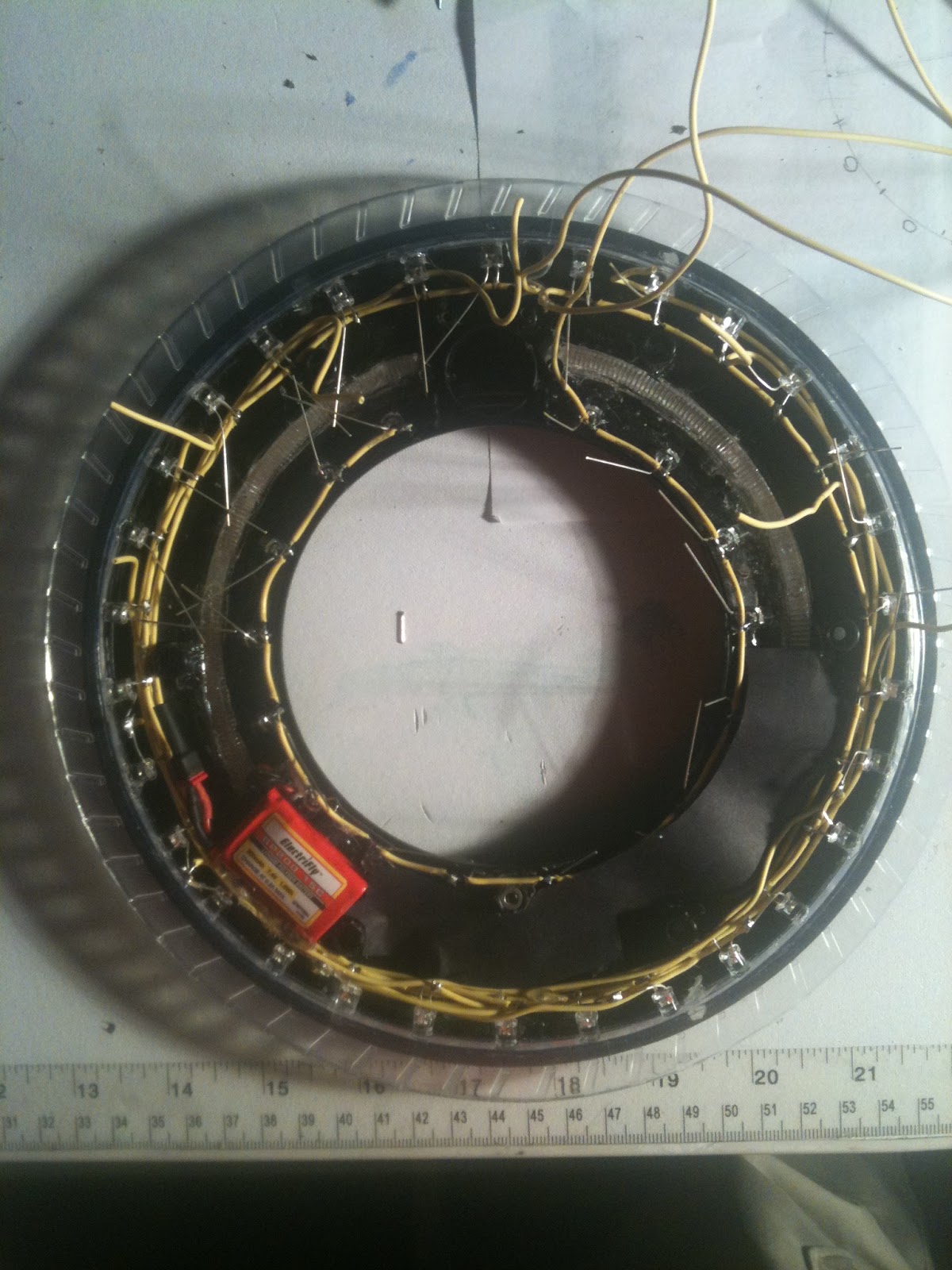 |
| Experimenting with opaque paper |
 |
| Charging jack mirrors the factory slider switch hole! |
Sunday, February 13, 2011
Found this cool site to format my source code for posting on Blogger.
Anyway we had some issues come up with PET resin casts... they shrink slightly and have a tacky surface cure. This makes extracting them from the mold extremely easy but they fingerprint easy and they are just slightly smaller than the original. I was thankful it didn't turn out to be some oddity with the RTV Urethane molds! Those suckers are pricey!
So we are switching to polyepoxide (epoxy) resin - it is less brittle and correctly scaled for the small pours we do (2 ounces for the inner C rings each, 4 ounces for the blade). It also doesn't fingerprint and it is still clear as a bell!
The prices for these cast parts have been updated slightly with change in cost of materials.
Saturday, February 12, 2011
Updated picture of the hexagon fabric we have been shipping. See the "Hexagon Fabric" page to purchase!


Had some trouble programming the Arduino Nano from WinAVR using the same settings as I was doing directly to the ATMEGA168. I found some advise on this site that I will quote below to save you time...
Upload sketches with AVRDUDEThe bootloader is an 'stk500'-compatible, which means you can use good ol' AVRDUDE to program the arduino.
Just plug in the USB cable, then press the reset just before you start avrdude.
- Use -b 19200 to set the baud rate to 19200
- The device signature reads dont seem to work so you'll want to use -F
- The programmer type is avrisp
- The device type is -p m168
- The port is whatever the FTDI chip shows up as
Friday, February 11, 2011
Programming - 99% done... just working on the button release detection part. Will post source code here hopefully today!
 The LiPo I had ordered won't fit... not enough room between the LED's. I am scrambling now - I found one that I am sure will fit now but it is only 200mAh. Still should last 4 hours. The charger that came with the kit I ordered is not balancing which is sorta lame. So I am trying to find a charger today and a cable.
Sorry I have been bad about taking pictures! The front of the disc came out looking really sharp. LEDs are all mounted... still waiting for the controller (probably tomorrow according to USPS) and the jumper wires. Assuming I get all these parts I will be set to ship out the first completed disc next week!

Sorry I have been bad about taking pictures! The front of the disc came out looking really sharp. LEDs are all mounted... still waiting for the controller (probably tomorrow according to USPS) and the jumper wires. Assuming I get all these parts I will be set to ship out the first completed disc next week!
Tuesday, February 8, 2011

Monday, February 7, 2011
Got a lot done yesterday but started getting concerned about how difficult it would be to replace a battery in this thing - and the fact that I only expected the A23's to last about an hour.
A revisit to Thor's blog peaked my interest in Lithium Polymer. I found a couple of batteries with an average of 10 times the capacity that will fit. The only thing I am waiting to hear back on is whether I can integrate a charger circuit or not.

A revisit to Thor's blog peaked my interest in Lithium Polymer. I found a couple of batteries with an average of 10 times the capacity that will fit. The only thing I am waiting to hear back on is whether I can integrate a charger circuit or not.

Friday, February 4, 2011
Took the day off on Wednesday.
My wife forgot I lived there I have been in the basement so much! I updated the estimated delivery time on these because, although it is taking about as long as I expected, I don't have much free time. And if I do the wife and kids understandably want a share.
 |
| Row wires for the blade are complete! |
 |
| Still have plenty of room to work... |
Tuesday, February 1, 2011
Had some time to do wiring last night on the blade... it went really well! You must have a tool that can strip 20 AWG or smaller (mine does 22 AWG) but not the adjustable kind - needs to be the kind that has notches for all different sizes unless you strip wires all day for a living!


The soldering only took about 15 minutes so I imagine total soldering time to be about an hour but sizing and stripping the wire is time-consuming. I am going to try stripping the whole thing next time and then inserting heat shrink tubes between the LED leads and see if that is faster (basically replacing the insulation with my own).
The E-6000 adhesive works really well holding the flat-top LED to the inner rim of the blade (cast in PET, not the original).
I thought I had screwed up the layout at first by doing AK KA AK KA because the rim wire needs to connect the A then the K then the A then the K it might have been better to do AK AK AK AK because then the inner two leads (K A) could be tied together. Six of one, one half dozen of the other I suppose.
Subscribe to:
Comments (Atom)