Thursday, March 31, 2011

Limited time $2.86 (plus $5.00 shipping) Identity Disc mounts!

Monday, March 28, 2011


This was posted by someone who purchased my electronic kit.  They did an awesome job - I actually like what they did with the charging port better.  They used a higher gauge wire so they had more room and more flexibility with the wire so I am changing that out in future kits per their recommendation.  Their front C ring lights up in 8 segments instead of 16 because they didn't reverse the polarity on one of each of the column wires (either by choice or by accident).

Saturday, March 26, 2011

A lady that bought one of my kits recommended using the wire from a CAT5 bundle because it is an even higher gauge and has a thin insulation which would make it ideally flexible and small. I am going to start including that wire in the kits purchased on or after 3/26.

Wednesday, March 23, 2011


This is the most recent version I have been experimenting with.  It has two (2) microcontrollers (one for the front and one for the back and blade).  It makes it more expensive and not a whole lot brighter.  It also made it jam-packed and less of a DIY feat.

Monday, March 21, 2011

Friday, March 18, 2011

Posted inner-C layout template. The red lines should align with the LED mount points.  The circle should be 4.25 inches which is the internal diameter of the hole in the disc.


While we are talking about the hole in the disc this is a site I came across which is selling compatible disc mounts for costuming.

Wednesday, March 16, 2011

Posted first of our disc preparation instructions...
https://bitbucket.org/orpex/identity-disc/wiki/Post_Removal

Made a new mold for the blade... the old one broke and I think it is because I cut it along the rim so that air bubbles could escape. The mold only holds up as long as the edge touching the epoxy is super smooth (and lubricated with dry silicone).

Tuesday, March 15, 2011

What you have when finished cleaning up the back.

Place the battery door back in and glue it in place from inside using the black hot melt glue.


Next step is to route out the back C ring.  

A couple of gotchas - always work the Dremel bit towards you (pulling the material) on the right side of the bit (outside edge of the track).  Turn the disc around to work the inside track.  Keep it moving... if it sits for too long it will get hot and it is easier to make a mistake.  Use a anti-slip pad (dollar store) on the work surface to help protect the disc and to help you hold everything still.

Next step - Remove front C track - Approximately 45 minutes

First, pop out the existing plastic piece from inside starting at an end and working your way down using the various slots in the track to get access.

Don't try to pull the piece out if you intend to keep it - there is a weak spot where the two LEDs used to fit.

Front half track removed.  Keep the cutting disc parallel to the disc surface and be mindful of where the other side of the cutting disc is... the material for the face of the disc is not super thick.

Monday, March 14, 2011

Instructions for electronic kit...

Tools you will need are mid-size Philips, small slotted, and Dremel with plastic cut-off disc.
Additional tools are adequate lighting and safety glasses.

Your disc as it appears out of the package

Locate and remove the 6 screws and battery door cover screw.
I recommend you store the screws in a plastic ziploc bag so you don't lose them.

Remove the battery door and the 6 batteries.  

The batteries need to be gently pried out using a small slotted screwdriver and properly stored or disposed of.

Turn the disc over and remove the top half (pry your fingers gently between the blade and the top half).


In the case of Kevin Flynn's disc you will need to set aside some black construction paper pieces at this point.
Dislodge the 6 LED's from the plastic blade (blue above).
Remove the plastic blade (blue in this picture) from the back of the disc.
If you are reusing your blade you must cut the flanges off at some point with a box cutter.

Remove the 5 screws highlighted and set the plastic switch aside (preferably in a plastic ziploc).

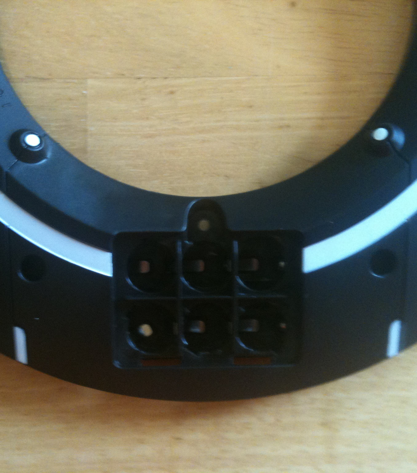
Disconnect the 4 wires at the battery compartment.
Lift up the main PCB so you can cut the tactile switch wires as close as possible.
Remove the tactile switch at the top and cut the two leads as close to the PCB as possible (we will be reusing this switch).

Remove the impact sensor, PCB, speaker, and LEDs as a harness.

Using the cut-off disc, carefully cut each of these flush.  
Be conscious of where the other end of the cutting disc is at all times.
Try to find an angle that leaves you parallel to the disc surface when cutting (sometimes it means removing another post before you can remove the one you picked to tackle).
In a few cases this isn't possible you can simply sand it to oblivion.
Wear safety goggles and adequate lighting is a must.


To be continued...

Tuesday, March 8, 2011


This is the DPDT slider switch that is included
These come with ICSP header pins which must be cut flush

Monday, March 7, 2011

LED Datasheet

Updated bitbucket wiki to reflect a parts list.  When you receive your kit you can use this to verify everything is included!

Friday, March 4, 2011

Although I like the scanning technique for the LEDs I was not as happy with their final brightness.  A friend at work suggested I slow the scan rate down a little.  I changed the interrupt from Clock/64 (from prescaler) to Clock/256 (to make it obvious).  Now I can see the scan rate but the brightness appears unaffected.


I am considering for V2 to employ 2 microcontrollers... $20 more but twice as bright.

Tuesday, March 1, 2011

The pictures below are what you get in the kit...


I just found out about these today... I think this will look a lot tighter holding the inner-C rings in place... we aren't talking about space shuttle tolerances here!

Black hot melt glue sticks!